Hi. The following questions are more on the dev side:
-
Is there a way to plot or extract the measured values by the reference photodiode? I checked relevant export files but it goes from measured OD to normalized without logging the reference OD value.
-
I want to see these ref values because, after some tinkering, I noticed that the ref photodiode minimally impacts the normalized OD readings. A quick look at the od_reading.py shows these reference values going through an exponential moving average. Is there a way to turn off or edit the degree of EMA smoothing?
-
Is there a straightforward way to change OD sampling frequency from 5 seconds to say 5 minutes? I am turning off an external air pump and letting the bubbles dissipate every reading
Oh plotting the reference: you can more easily do this.
In your config, change:
[od_config.photodiode_channel]
# Default IR photodiode channel(s) to use and its angle relative to the IR LED(s),
# OR choose the reference photodiode using the keyword REF.
# Only valid angles are {45, 90, 135, 180}
# Only allowable channels are {1, 2}
1=REF
2=90
to
[od_config.photodiode_channel]
# Default IR photodiode channel(s) to use and its angle relative to the IR LED(s),
# OR choose the reference photodiode using the keyword REF.
# Only valid angles are {45, 90, 135, 180}
# Only allowable channels are {1, 2}
1=90
2=90
After restarting od_reading job, this will “trick” the software in thinking there are two PD measuring at 90 degrees, and plot them both. Just remember which one is actually in the REF position. Note that the software will skip any reference normalizations now, here’s the code for how that is determined.
Ah lesson learned, always check config file first. Thanks for the detailed response  Here is a more interesting question:
I am playing around with using my own LED/PD combo. One issue I face is that my light source is much “brighter” relative to the PD when compared to the IR set that comes with the pio. This causes a saturated PD which is irresposive at initial culture densities.
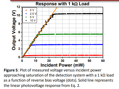
One way to prevent saturation is to increase the voltage supplied to the reverse-biased PD. The tradeoff here would be increasing noise floor with increasing supplied voltage (worse low light performance). Is it possible to alter the voltage delivered to the PD through software via the DAC? Could this voltage be dynamic so that it benefits from both low light/low voltage and bright light/high voltage scenarios (decreased as culture becomes denser)?

A quick look at the git issues I see you’ve had an issue with saturation affecting the DAC. Could this be the fix?
There’s no direct connection between the DAC and the PDs - you could hook one up, but it would be a tight squeeze and require careful hands.
There are a few alternate solutions I can think of:
- the PDs use a trans-impedance amplifier with a 1M ohm feedback resistor (something like that, between 1M and 2M). Swapping this resistor for a much smaller one would reduce the sensitivity. Actually swapping is a lot of work, you could just put a much smaller through-hole resistor in parallel.
- More of a hack: physically obscure the PD. For example: behind a 3D printed wall, or acrylic, or with fabric.
Unfortunately there’s not any software solution here.
1 Like
I was worried that would be the case. The physical obscurity was my backup plan. Already printing. I do not have the tools or skills to solder on this scale.
