Has anyone tried using a stepped motor instead of a DC motor peristaltic pump for dosing to achieve higher low-flow accuracy? If so please share your wiring configuration to the motor driver.
If not I will try to figure it out and report back how I did it.
At the small chance someone else wants to do this heres how I did it.
I used a TB6600 motor driver because I had it on hand but you can use a smaller one depending on your motor size. They have the same pins and many wiring tutorials on YouTube. I ordered a KPHM100 but so far tested it with a stepper motor I had on hand.
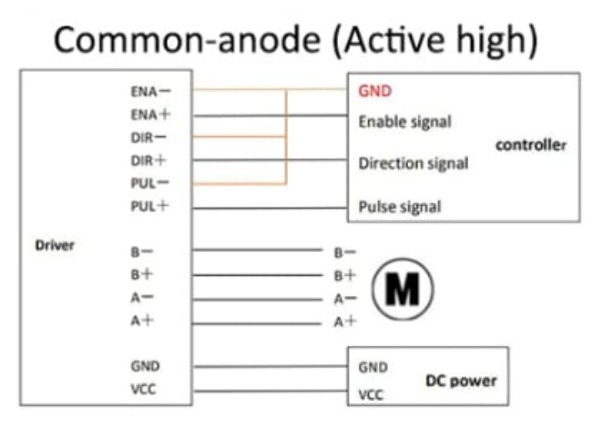
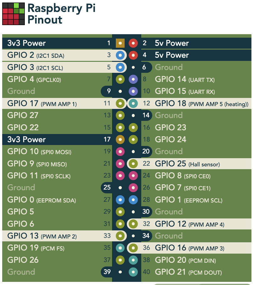
To get it working I connected GND to pioreactor/RPI Ground header pin and connected PUL+ directly to GPIO13 header pin which gives a signal to pioreactor PWM 2 channel. This allows you to use the dosing code as is by choosing a specific frequency for speed and 50% duty cycle in your calibration.
I tried connecting to the PWM 2 channel directly but that doesn’t work I believe because it is a current controlled connection. You can use any PWM channel upstream header pin to whatever you have the pump set to in your config file.
I will likely modify the dosing code to use another free GPIO pin so as not to take up the pioreactor PWM channel. I will also use another free GPIO pin for the ENA+ to disable the motor between dosing.
Do you mean the input control on the stepper driver? If so yes it does work even though amazon listings dont say they do. If you want to recreate this id recommend a smaller driver anyways this is oversize for this pump I just had it on hand but regardless you can choose current using dip switches.
One other thing i dont love abt this driver is that it is enabled when there is no voltage difference between the ena pins. So if the pi is off for any reason and the driver is on the motor will be energized (not moving just hum). I added some code to pump.py to turn off/on ena pin during normal operation
You could but theres no need for the extra microcontroller and extra code to have the RPI and microcontroller communicate. There are enough free pins to run a stepper motor driver. I would only recommend using a second microcontroller if you need more that 1 pump being stepper motor driven.
Only using stepper motor pump for media addition. Waste removal is run in the pio setup to drain culture up to certain height dictated by the waste removal tube.
True — you could do it that way, but keep in mind that the Raspberry Pi isn’t a real-time system, so there might be small timing mismatches when controlling the stepper directly, unlike microcontroller boards, which operate in almost real time. For the pump’s PWM signals, this isn’t an issue because they rely on dedicated hardware or microcontrollers to maintain precise timing. In my case, I’m interested in running the chemostat as continuously as possible at a low dilution rate, where timing could be important. I haven’t tested it yet, though — looking forward to hearing about your experience with this.
My memory isnt super fresh on this topic, but from what I remember the pi has some pins that can do hardware pwm and others that can be configured for software pwm. You want to go with one of the hardware ones in that case. They are specified in the code base. They may already be in use by stock pioreactor setup for heating or the pumps already. But again youll be limited by number of stepper pumps.
If you are just adding one pump and one stepper driver then I can look up how we did it on our setup. Requires some jerry rigging at least with the stepper driver we chose as you have to power (or disconnect depending on wiring) the ENA pin on the driver every time you start the job or every time you turn on the pump if its running intermittently.
From your reply, it sounds like you want to dose at a very slow rate continuously (chemostat). I would worry too much about the clock, but I’d still recommend the hardware PWM, as idk how software PWM performs with everything else running in the background. If anything, it is more important that you get the right stepper driver and the right pump. The smaller the peristaltic tubing, the more accurate it will be. As for the driver, you can change the step size pulse/rev. So get one that can be set to a high number. The one im using goes to 6400 step/rev which is overkill accuracy for my large volume reactor but I see ones online that go up to 25k step/rev which would be more accurate.
Thank you for your reply. I hadn’t thought of using the Pi’s GPIO pins directly — good idea! One stepper motor is enough for what I have in mind for now.
Any comments are welcome, especially regarding the software side. Can I hijack the signal from a GPIO pin intended for a standard PWM-controlled pump on the Pi and activate it without having a DC pump connected? Maybe that could avoid modifying the code altogether?
Also, why did you disable the ENA pin? My driver uses 1/16 microstepping (A4988 3200 steps per toration). I suspect that, at some point, the peristaltic pump’s tubing pocket dynamics will influence precision more than the ability to drive it very slowly. Comments also welcome on this.
Basically I have it so that one of the original pump connectors goes directly to the stepper driver PUL pins. This works since original pumps are driven using PWM as well. The driver is powered using external PS which drives the pump. So the PWM signal from pioreactor is just for stepping. You cannot avoid altering the code. You basically set it to duty cycle of 50% and frequency will depend on your microstep size and desired flowrate.
The wiring of the ENA pin and implementing into code was actually the trickiest part to figure out. The reason why you want to use ENA pin: ENA pin basically tells the driver when to send voltage to the pump. The way these steppers work is they can usually be wired in two configuration, either when ENA has power then it transmits to the motor or when there is no power it transmits to the motor. You can of course choose the later which removes the need to incorporate it into the code, but the issue is any time the driver is plugged in, whether you intend the pump to be rotating or not, its motor will be receiving power. If there is no PUL signal telling the driver to step the motor, the motor will still be energized (but not spinning) which makes it resist motion (important for applications when there is a constant load on the shaft that you might want to resist), not needed for this application. This places unnecessary ware on the motor and causes an annoying humming sound. Jeremy Fielding has a good youtube tutorial on this.
The more rollers the peristaltic pump has the smaller the tubing pocket. Usually either 3 or 4 rollers. If your volumes are extremely small you could alternatively consider a piston or syringe stepper motor driven pump. Once you get the driver working I would modify the pump calibration script for the volumes/flowrate you want to achieve and see if the stepper peristaltic pump is accurate enough.